GEOTECHNICAL ENGINEERING
CELBRIDGE
HomeGround improvementStone column design

Stone Column Design in Celbridge – Ground Improvement for Cohesionless and Soft Soils

Practical geotechnics, field-tested.

LEARN MORE

The geotechnical contrast between Celbridge’s eastern housing estates near the Liffey and the western lands rising toward the M4 is sharper than many developers realize. On the river side, boreholes often reveal layers of soft alluvium and loose sands extending to depths of 4 to 6 metres, while the higher ground west of the town center transitions into stiffer glacial till. This variability means that a standard shallow footing design that works near the Celbridge GAA club may be entirely unsuitable for a light industrial unit planned closer to the riverbank. A ground improvement strategy using stone columns becomes a highly effective solution, creating stiffened composite ground by introducing compacted gravel elements that densify the surrounding soil and provide controlled drainage. When the in-situ permeability of a site indicates poor consolidation rates, the drainage function of stone columns becomes as critical as their load-bearing role.

A well-designed stone column grid does more than carry load – it fundamentally changes how pore pressures dissipate during a seismic event.
Our service areas

How we work

On several projects near the old mill buildings by the Liffey, the in-situ material at depths between 2 and 5 metres shows fines content that would disqualify it from effective vibro-compaction alone. This is where a properly dimensioned stone column grid, designed with the Priebe method and verified through settlement analysis, produces a marked improvement in bearing capacity while accelerating primary consolidation settlement. The typical column diameter in Celbridge ranges from 0.6 to 1.0 metre, with area replacement ratios between 15 and 30 percent depending on the target post-treatment modulus – a parameter we validate with post-installation load tests. In coarser deposits found along the Maynooth road corridor, combining these columns with a load transfer platform creates a foundation system that can support between 150 and 250 kPa without excessive total or differential settlement. For projects where liquefaction potential is a concern, integrating the ground improvement design with a detailed liquefaction assessment allows us to specify column spacing that both mitigates pore pressure buildup and satisfies the serviceability requirements of the structure above.
Stone Column Design in Celbridge – Ground Improvement for Cohesionless and Soft Soils
Technical reference — Celbridge

Site-specific factors

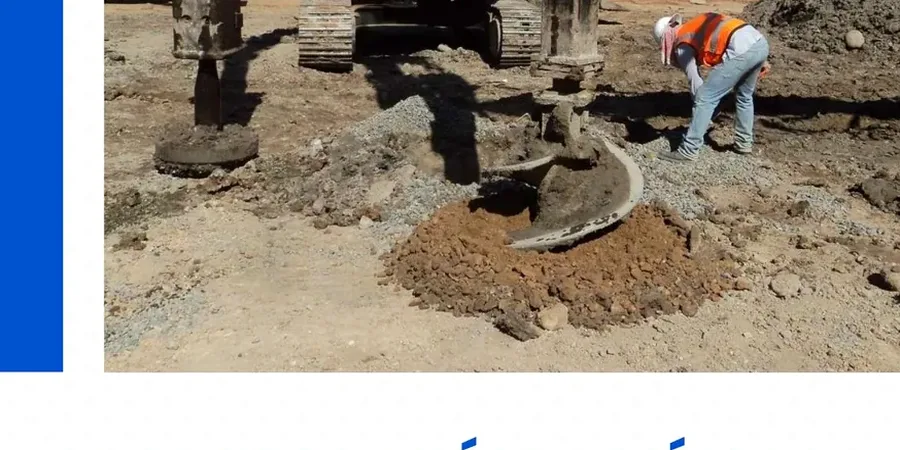
A crawler-mounted vibroflot with a hydraulic leader mast positions itself over the grid point, and the vibrator penetrates under its own weight assisted by compressed air or water jetting. In the alluvial pockets south of Celbridge’s Main Street, the probe can sink rapidly through the first three metres of soft silt before meeting resistance in the underlying gravels, and the operator must read the ammeter carefully to identify the transition zone. The real risk during installation lies in lateral displacement of the surrounding soil if the column spacing is too tight or the replacement ratio is miscalculated – a condition that can heave adjacent footings or crack shallow utilities. Worse still, if the fines content exceeds 20 percent and the soil cannot drain the excess pore pressures generated during compaction, the columns may end up surrounded by a remolded, weakened matrix instead of a densified one, which directly undermines the design friction angle and reduces the composite stiffness below the values assumed in the settlement analysis.

Need a geotechnical assessment?

Reply within 24h.

Email: contact@geotechnical-engineering.co

Regulatory framework

BS EN 14731:2005 – Execution of special geotechnical work. Ground treatment by deep vibration., IS EN 1997-1:2005 (Eurocode 7) – Geotechnical design. General rules., Priebe, H.J. (1995) – The design of vibro replacement. Ground Engineering.

Reference parameters

ParameterTypical value
Typical column diameter0.6 – 1.0 m
Area replacement ratio (Celbridge alluvium)15 – 30 %
Design methodPriebe (Heinz J. Priebe, 1995)
Target bearing capacity (post-treatment)150 – 250 kPa
Column materialClean angular gravel, 25-75 mm
Installation depth (typical)4 – 12 m
Post-installation verificationPlate load test (BS 1377) or CPT

Frequently asked questions

What is the typical cost range for a stone column design in Celbridge?

Depending on the number of columns, grid area, and required investigation depth, the design phase for a vibro-replacement system in Celbridge ranges between €1,500 and €5,230. A smaller residential extension on marginal ground would sit at the lower end, while a full commercial or light industrial building with extensive site investigation and multiple load test specifications would approach the upper figure.

When are stone columns a better choice than rigid inclusions or piling?

Stone columns are particularly effective when the primary goal is to improve the ground mass rather than bypass it entirely, especially where the fines content is below 20 percent and drainage is beneficial. They reduce total and differential settlement while maintaining a relatively flexible foundation system, whereas rigid inclusions or CFA piles would be specified when loads are heavier or when settlement tolerances are extremely tight, such as for sensitive equipment foundations.

How do we verify the column grid is performing as designed?

Post-installation verification typically involves a combination of plate load tests on individual columns and on groups of columns, following BS 1377 procedures. We also use CPT soundings through the column center and in the soil between columns to measure the improvement factor, comparing the tip resistance and sleeve friction before and after treatment to confirm the design assumptions.

Can stone columns address liquefaction risk in Celbridge?

Yes, and this is one of the most relevant applications for the alluvial deposits near the Liffey. By installing stone columns at a spacing calculated to limit excess pore pressure generation during a design seismic event, the columns act as vertical drains and densify the surrounding sand. The design must reference a site-specific liquefaction analysis that determines the target SPT N-value or CPT tip resistance needed to eliminate the liquefaction potential at the design earthquake magnitude.

Location and service area

We serve projects across Celbridge and surrounding areas.

View larger map